
U.S.S. Saratoga Engineering
Created by Rear Admiral Zseeq on Tue Dec 26th, 2023 @ 2:37am
Engineering
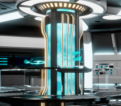
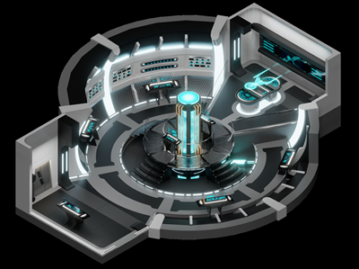 Main Engineering on the U.S.S. Saratoga-C serves as the heart of the starship, a two-deck cathedral of high technology where the vessel's immense power is generated, regulated, and distributed. Located deep within the secondary hull, this facility is dominated by the Warp Core, a towering assembly that spans the height of the compartment and pulsates with a steady, rhythmic blue glow. The engineering space is a masterclass in functional density, utilizing a vertical gallery design that allows personnel to monitor core harmonics from multiple vantage points. The central Matter/Antimatter Reaction Assembly is encased in heavy Duranium shielding, with magnetic constriction segments visible through reinforced ports, providing a direct view of the high-energy plasma generation that drives the ship across the stars.
The floor of the lower level is divided into specialized zones to facilitate complex maintenance and rapid response. This primary deck houses the majority of the department's workstations, arranged along the perimeter bulkheads in recessed alcoves. These stations include specialized diagnostic terminals for the Impulse Propulsion Systems, Warp Propulsion System, Quantum Slipstream Drive, and the shipwide power grid. At the center of the lower level, a distinctive area surrounded by hazard striping and safety railings allows for close-range monitoring of the reaction chamber. Because the Saratoga-C is designed for long-range, independent operation, these consoles can be reconfigured in an emergency to emulate Bridge functions, effectively turning the lower deck into a secondary command hub.
 The upper level consists of a wide, industrial gantry that wraps around the Warp Core, accessible via integrated ladders. This elevated platform serves as the primary command post for the department. Rather than a separate office, the Chief Engineer’s workstation is located directly on this gantry, providing the officer with a commanding, unobstructed view of the entire facility and the core’s upper injectors. Mounted prominently on the bulkhead of this upper level is the Master Situation Display, a large-scale visual diagnostic center that highlights the real-time operational health of the starship.
Safety is a paramount design consideration throughout the two-deck complex. Heavy isolation doors and containment forcefield generators are strategically placed to snap shut instantly in the event of a plasma breach or Warp Core instability. This ensures that the Engineering staff remains protected even during the most severe mechanical failures. With its blend of rugged structural supports, exposed conduits, and sophisticated LCARS interfaces, Main Engineering represents the pinnacle of Federation design, ensuring the Saratoga-C remains a resilient and formidable explorer in the farthest reaches of the galaxy.
Faster Than Light
Quantum Slipstream Burst Drive Propulsion System
 The Saratoga’s Quantum Slipstream Burst Drive is a specialized, retrofitted propulsion technology developed by Starfleet to bypass the severe resource limitations associated with full-scale Quantum Slipstream drives. While the original technology, first encountered by the U.S.S. Voyager in the Delta Quadrant, relies on rare and difficult-to-synthesize Benamite Crystals to regulate the quantum field, the Burst Drive serves as a functional stepping stone that enables limited-duration slipstream travel. Unlike full-scale drives that require sustained field maintenance, the Burst Drive configuration is designed for episodic use. It enables a vessel to project a Slipstream Conduit for exactly 30 minutes, allowing for travel of approximately 150 light-years before the system automatically shuts down. Generating the conduit involves routing energy from the Quantum Drive, located in the ship's Stardrive to the Deflector Dish, which emits high-energy tachyon bursts to penetrate the quantum barrier.
Because the Burst Drive is an experimental and demanding system, it requires intensive resource management. Maintaining the slipstream geometry demands significant computer processing power to perform the complex, dynamic calculations necessary for the vessel. Navigation, Helm, and Operations officers must continuously monitor and adjust the phase variance of the quantum field to ensure conduit integrity, while engineering must maintain a Quantum Field Focus Controller to keep systems in operational mode. To mitigate the extreme gravimetric shear, the vessel must project a Structural Integrity Field through the Navigational Deflector, and a Chroniton Integrator is required to maintain temporal sync, preventing damage from temporal stress. The Multidimensional Wave-function Analysis module is also essential for detecting subspace rifts or temporal distortions that could risk deactivating the drive system. The system is prone to erratic power fluctuations, which can flood the ship's standard Warp Propulsion System with tachyons, creating a risk of a Warp Core breach if operating in connected flight mode.
The Burst Drive remains a high-maintenance technology, requiring nearly 12 hours to fully reset and recharge after every deployment, and it is highly susceptible to failure if subjected to constant use. Because the traditional Warp Drive remains an independent system, Starfleet crews can safely operate under standard Warp parameters between slipstream bursts. Failure to properly regulate the system results in a catastrophic collapse of the slipstream threshold, which violently ejects the ship back into realspace and frequently causes severe hull damage or the total destruction of the vessel.
Warp Propulsion System
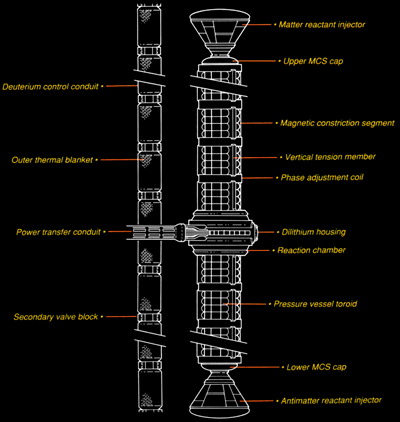 At the very heart of any starship is its Matter/Antimatter Reactor (M/AMR), more commonly known as its Warp Propulsion System or Warp Drive. This device allows interstellar travel to occur and works by annihilating antimatter with matter in a dilithium-controlled reaction, which is then channeled for power and to propel the ship on its journey. Each Warp Drive contains has three primary components: the Matter/Antimatter Reaction Assembly; the Power Transfer Conduits; and the Warp Nacelles.
Matter/Antimatter Reaction Assembly
The Matter/Antimatter Reaction Assembly is the component of the Warp Drive where matter and antimatter are introduced to one another, generating power through the annihilation of the particles. The assembly contains three parts: the Reactant Injectors, the Magnetic Constriction Segments; and the Matter/Antimatter Reaction Chamber itself. These component parts are combined into a single Warp Core with the Matter Reactant Injector located at the top of the Core and the Antimatter Reactant Injector located at its base. The Matter Reactant Injector uses deuterium fuel and the Antimatter Reactant Injector uses an antimatter fuel to create the powerful reaction powering the vessel. Similar in design and function, the Antimatter Injector is specially modified with magnetic suspension fuel tunnels, preventing the antimatter from coming into contact with normal matter outside of the reactor. Construction advancements have permitted a six-lobed injector assembly design that allows for seven reactant streams to insert their fuels into the Magnetic Constriction Segments of the Warp Core, allowing the materials to be injected into the Matter/Antimatter Reaction Chamber.The Matter/Antimatter Reaction Chamber channels the flow of the distinct fuels toward the Dilithium Crystals that manage the reactants. The only substance that does not react to antimatter when subjected to a high-frequency electromagnetic field, Dilithium is stored within the Dilithium Articulation Frame within the Warp Core and allows the matter and antimatter to pass through the crystal’s structure without touching it. Computer controlled rotation allows for the manipulation of the manner in which the reactants meet within the Dilithium Articulation Frame, allowing for greater control and a "cleaner" power source. This allows the fuels to come into contact with each other, which are quickly annihilated in a reaction producing an enormous amount of energy quickly. Creating an intense plasma, this energy is directed to the Power Transfer Conduits immediately afterward.
Matter/Antimatter Fuel Storage
Primary Matter Fuel Storage aboard the Saratoga is provided by a colossal Deuterium Storage Tank within the vessel's Stardrive Section. Providing fuel to both the Impulse and Warp Propulsion Systems, the fuel tank is loaded with slush deuterium that is fed into the propulsion systems through reactant injectors. Normally the Deuterium Tank is loaded through supply lines located on the aft dorsal of the Stardrive Section and will last for approximately five years when fully loaded; however, internal equipment within the Warp Nacelles known as the Bussard Collectors will collect stray Hydrogen that can be used to create replacement Deuterium.Located in the Stardrive Section, the Antimatter Storage Pods are magnetized self-contained storage units designed to contain the antimatter fuel used by Saratoga during its Warp reaction. Consisting of multiple pods, the Antimatter Storage Assembly uses advanced containment fields to isolate the fuel within the pods from coming into contact with normal matter, preventing a catastrophic reaction. Loaded from transport vehicles during servicing at a Starbase, Saratoga has been equipped with an antimatter generation system that can produce the fuel should the vessel be unable to return to base.
Power Transfer Conduits and Warp Nacelles
The Power Transfer Conduits split the plasma generated by the matter/antimatter reaction into an energy stream for the Warp Nacelles. Magnetic constriction is used to direct the energy stream toward the Warp Nacelles, with specialized Electroplasma System (EPS) taps allowing energy to be diverted to power the ship’s systems. The Power Transfer Conduits end within the Warp Nacelles themselves, which consist of three parts: the Plasma Injection System, the Warp Field Coils, and an Emergency Separation System.Located within the Warp Nacelle, the Plasma Injectors divert plasma into the Warp Field Coils that allow for faster than light speeds to be achieved. The Intrepid II Class is fitted with 18 Warp Field Coils in each nacelle that are made of tungsten-cobalt-magnesium and verterium cortenide. Nacelles use the energy generated by the Warp Core to shift the energy frequencies carried by the plasma deep into subspace, creating the Warp Field through the sequential firing of the Coils, causing the Warp Field layers to interact with one another. Currently, Starfleet employs Variable Geometry Warp Nacelles on all vessels, allowing the ship's engineers to generate a more energy-efficient subspace field with less waste as well as adjust its subspace field in highly turbulent spacetime. These advances in Warp technology allow Saratoga to maintain stability at higher speeds for longer periods of time than most of her Starfleet cousins; however, these advancements have come at the cost of potentially causing microfractures within the hull at high speeds that could lead to catastrophic breach. To compensate for this, Starfleet has installed failsafe software into the nacelles that will cause the ship's Secondary Coils to disengage to automatically decrease speed unless overridden by both the Captain and Chief Engineer.
Located on the forward edge of the Warp Nacelle, the Bussard ramscoops are used to “sweep” interstellar space with a magnetic field. This field gathers hydrogen atoms in the event of a fuel shortage, allowing the ship to generate its own deuterium fuel. As needed other gases can also be collected by the ramscoop, or the crew can flush the ramscoops to eject the collected gases. This process also allows the crew to vent plasma from the Warp Nacelles in an emergency to prevent a catastrophic overload that would destroy the spacecraft. Should venting plasma not work, the Emergency Separation System can be engaged by the crew or automatically to eject a nacelle.
Slower Than Light
Impulse Propulsion System
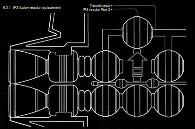 Used for navigating solar systems, traveling within gravity wells, or engaging in sub-light combat, the Impulse Propulsion System allows the Intrepid II Class to move at high velocities without engaging the Warp Drive. The ship features twin Impulse Engines housed within the Warp Nacelle Pylons, with specialized baffles used to help scatter their energy signatures for stealth missions. Standard flight protocols strictly limit impulse velocities to 0.25c (one-quarter the speed of light) to avoid severe relativistic time-dilation and mass complications; with the engines operating on approximately one-millionth of the energy required for warp travel.
The engine functions through a four-stage process beginning in the Impulse Reaction Chamber, where cryogenic slush deuterium fuel is ignited in a proton-antiproton fusion reaction. This fusion process generates high-energy plasma that provides both physical thrust and a vital secondary power supply for all onboard systems. The resulting plasma feeds into a cylindrical accelerator, which further excites the particles. During this stage, the computerized command coordinator can divert energy via Electro-Plasma System (EPS) taps and Magnetohydrodynamic (MHD) conduits to power the ship’s computers and internal networks if the main warp reactor is offline.
Propulsion efficiency is achieved through the Driver Coil Assembly, which performs a low-level space-time continuum distortion. This "continuum slippage" reduces the ship's apparent internal mass, allowing it to move a total mass displacement of over four million metric tons that would be impossible through raw Newtonian reaction alone. Finally, the Vectored Exhaust Director expels the reaction by-products through movable vanes to provide steerable thrust.
Reaction Control System
The Reaction Control System (RCS), also known as “thrusters,” are used for low-velocity propulsion, station-keeping, and maneuvering control in space.Located at strategic points around the hull of the starship, the Primary RCS engines aboard Saratoga use microfusion or gas-fusion reactions, drawing deuterium fuel to produce propellant. This propellant is then fired through vectored nozzles to create thrust in a specific direction, often in coordinated bursts, to change the ship's orientation.
Speed Chart
Warp Speed Distance Chart | |||||||
(400,000 km) |
(12 billion km) |
(5 ly) |
(20 ly) |
(8,000 ly) |
(2 million ly) | ||
| Full Thrusters | .00001 | 42.0 Hrs | 142.0 Yrs | 558,335.0 Yrs | 2,000,000.0 Yrs | 1.12 Billion Yrs | 223.33 Billion Yrs |
| Full Impulse | .25 | 5.38 Sec | 44.0 Hrs | 20.0 Yrs | 80.0 Yrs | 40,000.0 Yrs | 8,000,000 Yrs |
| Warp 1 |
1 | 1.3333 Sec | 11.1 Hrs | 5.0 Yrs | 20.0 Yrs | 8,000.0 Yrs | 2,000,000 Yrs |
| Warp 2 |
10 | 0.1323 Sec | 1.1 Hrs | 181.1 Days | 2.0 Yrs | 793.7 Yrs | 198,425.1 Yrs |
| Warp 3 |
39 | 0.0342 Sec | 17.1 Mins | 46.9 Days | 187.5 Days | 205.4 Yrs | 51,360.1 Yrs |
| Warp 4 |
102 | 0.0131 Sec | 6.6 Mins | 18.0 Days | 71.9 Days | 78.7 Yrs | 19,686.3 Yrs |
| Warp 5 |
214 | 0.0062 Sec | 3.1 Mins | 8.5 Days | 34.2 Days | 37.4 Yrs | 9,356.9 Yrs |
| Warp 6 |
392 | 0.0034 Sec | 1.7 Mins | 4.6 Days | 18.6 Days | 20.4 Yrs | 5,095.6 Yrs |
| Warp 7 |
656 | 0.0020 Sec | 1.0 Mins | 2.8 Days | 11.1 Days | 12.2 Yrs | 3,048.2 Yrs |
| Warp 8 |
1,024 | 0.0013 Sec | 39.1 Sec | 1.8 Days | 7.1 Days | 7.8 Yrs | 1,953.1 Yrs |
| Warp 9 |
1,516 | 0.0009 Sec | 26.4 Sec | 1.2 Days | 4.8 Days | 5.3 Yrs | 1,318.9 Yrs |
| Warp 9.2 |
1,649 | 0.0008 Sec | 24.3 Sec | 1.1 Days | 4.4 Days | 4.9 Yrs | 1,212.9 Yrs |
| Warp 9.6 |
1,909 | 0.0007 Sec | 21.0 Sec | 23.0 Hrs | 3.8 Days | 4.2 Yrs | 1,047.7 Yrs |
| Warp 9.9 |
3,053 | 0.0004 Sec | 13.1 Sec | 14.4 Hrs | 2.4 Days | 2.6 Yrs | 655.1 Yrs |
| Warp 9.99 |
7,912 | 0.0002 Sec | 5.1 Sec | 5.5 Hrs | 22.2 Hrs | 1.0 Yrs | 252.8 Yrs |
| Warp 9.9999 |
199,516 | 0.0000 Sec | 0.2 Sec | 13.2 Mins | 52.7 Mins | 14.6 Days | 10.0 Yrs |
| Warp 10 |
Infinite | ||||||
Categories: No categories found